Using TUFLOW FV and the GIS Mesher
28 August 2022
Solution guided meshing (SGM) is a semi-automated iterative process to generate a quality mesh with less effort than traditional methods. This process has been developed in the GIS Mesher developed by Rising Water Software, llc for use with TUFLOW FV models.
Table 1 provides a definition to key phrases in the paragraph above.
Table 1: SGM vocabulary
| Phrase | Definition |
| Semi-automated | The mesh is created using an algorithm with some user guidance. |
| Iterative | A series of steps are used to generate the mesh. |
| Solution guided | Each step uses the solution from the previous step. |
| Quality Mesh | For our purposes this means a mesh with mostly quadrilaterals, elongated in the direction of flow, with smaller cells where the depths are changing, and cell sizes are appropriate for the application. |
| Traditional methods | Mesh generators provide mechanisms for manually defining cell sizes and orientation within the domain. For large and complicated model domains, it may take significant effort to define this information manually. The solution guided approach aims to eliminate or decrease this effort. |
The question may be asked, why focus on trying to generate quadrilateral cells elongated in the direction of flow? Quadrilateral cells for the same edge length are more efficient than triangles. Because we are tracing flows across cell boundaries, the ideal configuration is for cell edges to be either in line with or perpendicular to flow. This can be achieved for all four cells of a quadrilateral but not the three edges of a triangle. Studies show that truncation errors are larger for triangular than quadrilateral cells. By elongating quadrilaterals in the direction of flow, we can have long edges parallel to flow where there is little need for additional resolution and shorter edges perpendicular to flow capturing the direction where the flow characteristics are changing more rapidly.
The traditional method relies upon user specified data for mesh construction. Using the traditional method, the GIS Mesher generates cells based upon a model boundary, break-lines that force cell breaks, and mesh size specifications. Other mesh generators may have different workflows for creating a mesh.
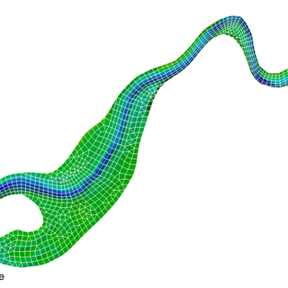
Figure 1 shows an example of a mesh building the traditional process.
Figure 1: Traditional Mesh Sizing
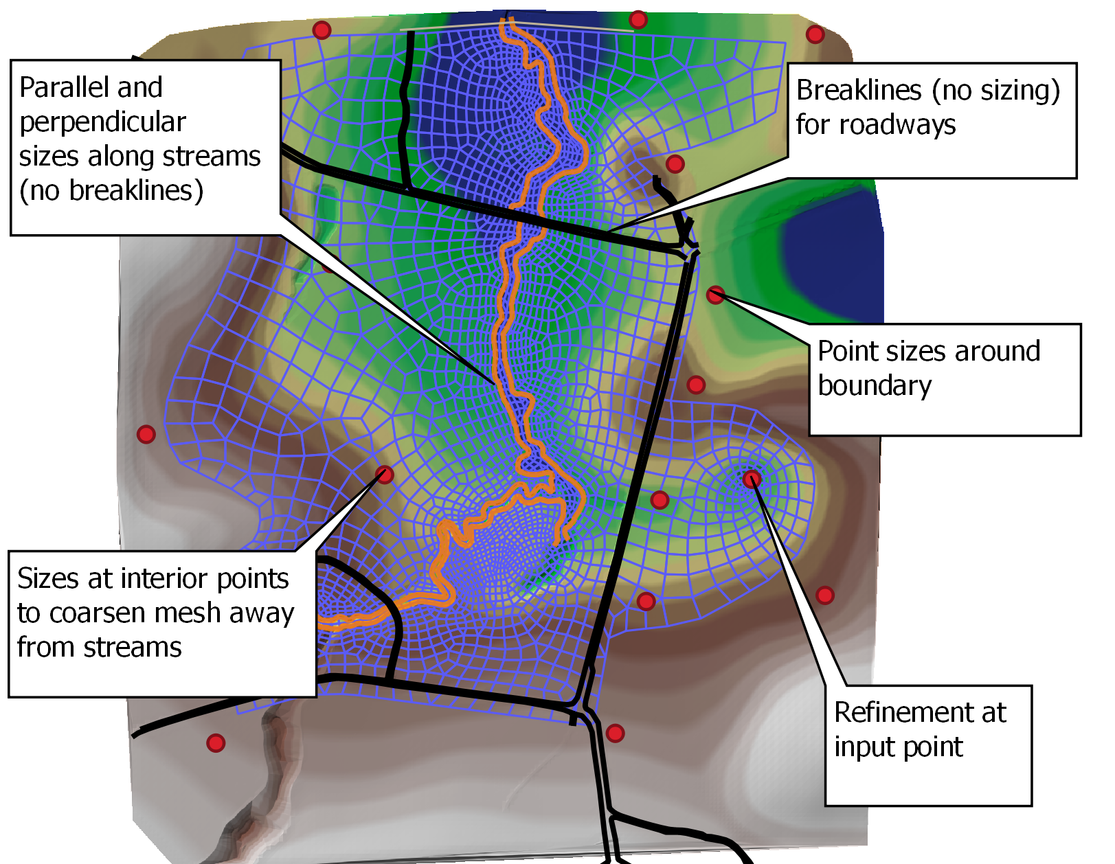
Note: This mesh is for illustrative purposes and not sized for a specific modeling application.
The traditional process works well and give users the ability to customize how the mesh is generated in each portion of the domain. However, the setup time for complicated models with many flow paths and complex floodplain flows can be significant.
The SGM process starts with an initial TUFLOW FV model with a simple mesh constructed using the traditional process. The starting mesh is generally quite coarse with a constant cell size which can be created quickly. The DEM representing accurately representing the underlying topography is also required.
The processes proceeds as follows:
graph TD
    A[Run TUFLOW FV Model] --> B(Evaluate mesh sizing for each cell)
    B --> C(Create modified sizes at cell centers)
    C --> D(Generate revised Mesh using updated sizes)
    D --> | Repeat | A
The key question to the SGM process is how size the mesh for the next iteration. SGM utilizes the WSE and velocity solution and the underlying DEM to determine where refinements are required.
Mesh sizes are determined by the change in relative depth within a cell. The relative depth is the change of depth as a ratio rather than an absolute value. The absolute value is not used because a change of depth 100 meters may not be important in the deep ocean even though a change of 1 meter may be critical for a shallow floodplain.
The size in the direction of flow is referred to as the primary mesh size and is based upon the change in relative depths and user defined parameters. Secondary sizes are the sizes perpendicular to the direction of flow and are computed based upon the primary size and the velocity for the cell using a user defined lookup table. The lookup table is constructed so that cells with higher velocities are narrower since these are typically channels with unidirectional flow. Cells with lower velocities are assigned a secondary size that generates cells that are more square.
Relative Depth Change Equation: DepthChangeRatio = (DepthMax-DepthMin)/DepthMin
Mesh sizes are determined by:
For each cell, determine minimum and maximum DEM elevation.
Compute minimum and maximum depths using the cell WSE (minimum depth may be negative indicating partial dry cell).
Compute the target primary cell size based upon relative depth change and whether some of the cell would have been dry.
Compute the target secondary cell size (perpendicular to the direction of flow) based upon the velocity magnitude.
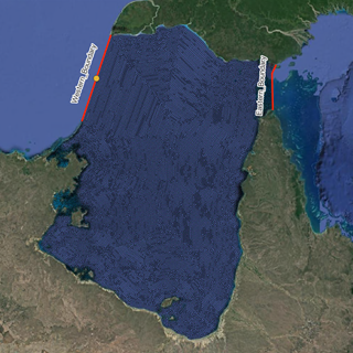
A model of the coast off Eastern Australia including the Great Barrier Reef demonstrates the power of the SGM process. The model includes a wide range of depths from shallow water near shore to the deep ocean. The reef is largely shallow with deeper channels that cut through the reefs.
The model uses publicly available bathymetry and is driven by tides in the deep ocean. The starting mesh is extremely coarse and is repeatedly refined to create a mesh that captures the complex geometry within the domain. While the SGM process works in any environment, this model exemplifies the power of the approach in large domains with complex flow patterns.
Creating a detailed mesh for this domain using traditional approaches would require significant effort to carefully adjust the mesh resolution and incorporate the required breaklines to capture the ocean shelf, islands, and the reefs with their curving channels. The SGM method generates a quality mesh with minimal effort.
Below are several sets of figures. Each set of figures has a tab for each iteration of the SGM process making it easy to switch between them to visualize how the meshing process proceeds.
Looking at the full domain (below) it is clear that cells in the deep ocean remain coarse while cells are added in other areas.


The figures below show a smaller portion of the domain. The transition from large cells in the deeper ocean to smaller cells along the shelf and near islands is clearly shown.


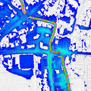
Below is an area of the Great Barrier Reef. The channel through the reef are not represented at all in the initial mesh but with each iteration provides better resolution of these channels. Not only do the later iterations refine the mesh to capture these channels but the cells are elongated in the direction of flow. The mesh also quickly transitions to larger cells once away from the channels. Capturing this kind of detail with the traditional process would be extremely time consuming.


There are global parameters that impact how meshes are sized for SGM as well as GIS layers that can be used to modify the sizes computed by SGM. Breaklines can be used in conjunction with SGM to enforce features as required. The global parameters control how sizes are revised for each meshing iteration. GIS layers can be used to force a minimum or maximum size in an area or to provide a size multiplier to coarsen or refine specific areas. Often these options are applied as an extra meshing step after SGM has completed. Sometimes the minimum and maximum sizes are used during the SGM process. For example, for the Great Barrier Reef model an island near the offshore boundary was intentionally not refined because refining it would increase runtimes for little benefit to the area of interest. The user guide and tutorials found on the developer website provide instructions on using the global parameters and GIS layers with SGM Rising Water Software Website.
SGM is an advanced meshing technique to generate detailed, high-quality, quad-dominant meshes that vary the resolution as needed with cells oriented to and elongated in the direction of flow. A number of user modifiable parameters help guide the SGM process to generate a mesh tailored to the specific application. SGM is especially powerful for complex models where manually defining mesh parameters would be time consuming.
N/A
To solve environmental problems in our rivers, lakes, estuaries and coastal waters, hydrodynamic models rely on a range of boundary condition forcings. For a complex model, there may be hundreds of necessary boundary conditions, each requiring input data for multiple parameters.
TUFLOW - Info
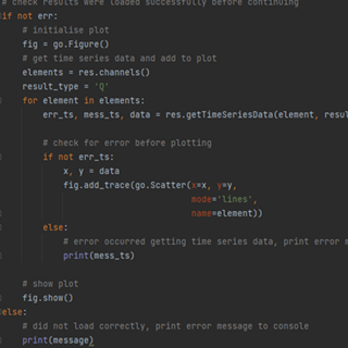
TUFLOW's PyTUFLOW toolbox provides an interface into the TUFLOW results file which allow the user to quickly and consistently process model outputs. An example is provided which integrates PyTUFLOW with the Plotly graphing library to produce interactive plots comparing modelled outputs with observed flow measurements.
TUFLOW - Info
Tips and Tricks: How to use diagnostic variables to speed up water quality model calibration workflow efficiency
TUFLOW - Info
The Pix Brook Flood Study is a multi-stakeholder options and feasibility investigation needing an integrated catchment wide model. TUFLOW was chosen due to its ability to represent surface water, fluvial and pipe networks within the one modelling software.